Weak weld lines: the order to follow to make them stronger
If a part always cracks along the same line, the problem is usually not the visible mark but two melt fronts that did not fuse hot enough or under enough pressure. A check order from cheap to expensive.
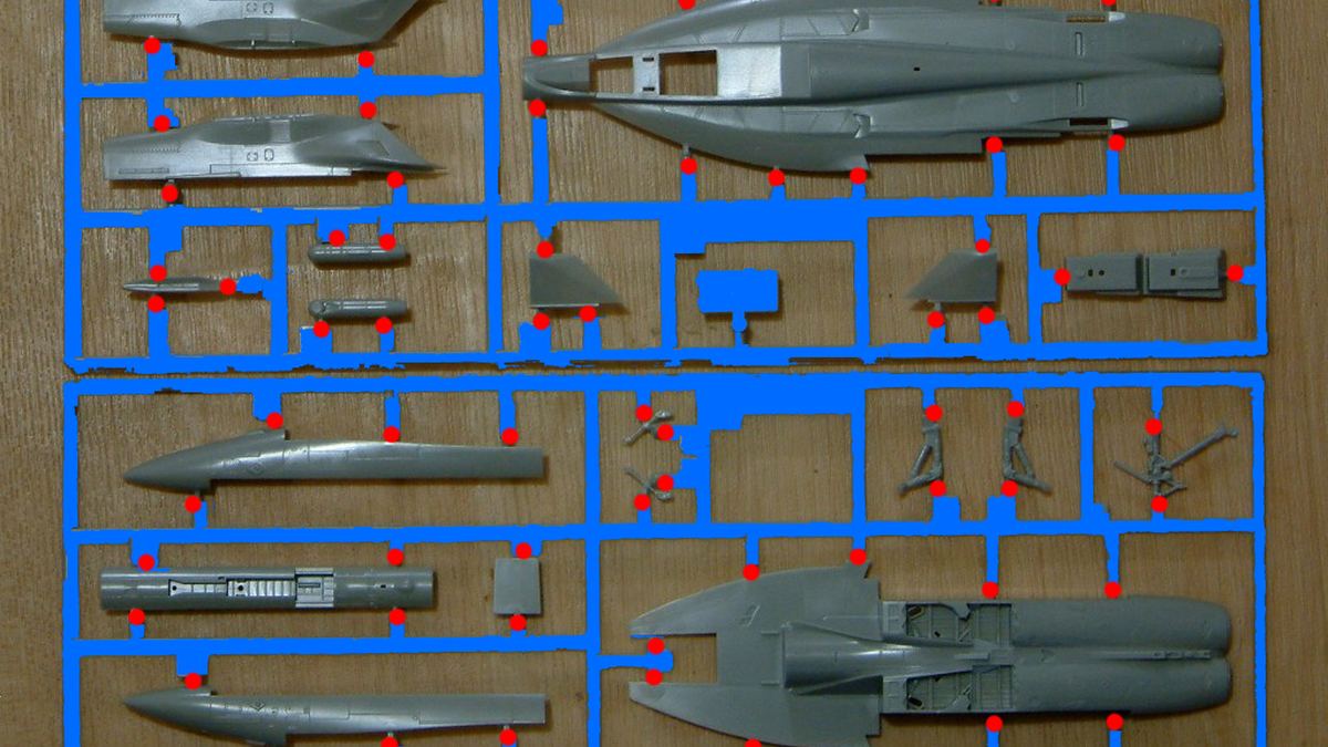
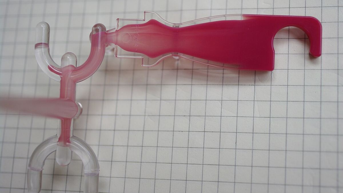
A weld line is the line left where two melt fronts meet inside the mold. It is unavoidable around holes, pins and inserts, and in parts with more than one gate. The real problem is not that it shows but that the area is weak: the part separates along the same line during assembly, screw tightening or a drop test. For the appearance and a short list of fixes, see the weld line page in the defect guide; this article focuses on strength.
Why is it weak?
The fronts that meet are melt that has already started to cool, with a skin on their surface. For the molecules to intermix across the interface, the fronts have to meet hot, under pressure and without trapped air between them. If one of the three is missing, the weld looks closed on the surface but stays weak inside.
- Fronts meeting head-on (behind a hole, between two gates) give the weakest weld.
- Fronts that keep flowing side by side (a meld line) mix better; the mark is fainter and the strength higher.
- In glass-filled materials the fibers align parallel to the weld plane instead of crossing it. Strength at the weld can therefore drop to about half of the strength away from it, and the gap grows with fiber content.
1. First see where the line forms
Run a short-shot series: reduce the shot size step by step and mold a few incomplete parts. They show clearly where the fronts meet, how far they travel before meeting and where air gets trapped. If the crack follows exactly this meeting point, the weld is the problem; if not, look for another cause first (sink, residual stress, moisture).
2. Can the air escape? (the cheapest and most often skipped step)
If the air between the fronts cannot escape, it blocks fusion and can even overheat and leave a burn mark. If there is no vent at the meeting point, have one cut; if there is, check that it is not clogged. Vent depth depends on the material (shallow for easy-flowing PA and PP, somewhat deeper for ABS and PC); a vent that is too deep causes flash. See burn marks and dieseling for details.
3. Make the fronts meet hotter
- Injection speed: Faster filling means less cooling on the way. It is usually the first and most effective setting for weld strength.
- Mold temperature: Heating the mold surface near the weld thins the skin on the front. Try the upper part of the recommended range for the material and follow the order in choosing mold temperature.
- Melt temperature: Raising it a little helps as long as you stay within the data sheet range. Going above the range degrades the material and makes the weld weaker.
4. Press the weld with pressure
Holding pressure presses the joined fronts together. If the V/P switchover comes too early, the weld closes at low pressure. First set the switchover point correctly, then set holding pressure and time with a gate freeze study. Pressure applied after the gate has frozen does not reach the weld.
5. Move the weld or make the fronts mix (mold changes)
If settings are not enough, the mold has to change:
- Gate location or number: moves the weld to an area that carries no load. A filling simulation makes this decision cheaper.
- Overflow well: a small pocket just beyond the weld point. The cold tip of the front flows into it, so hot melt meets and mixes at the weld. The overflow is trimmed off afterwards.
- Flow leader: locally thicker wall that steers the melt changes the angle at which the fronts meet; fronts that meet side by side instead of head-on weld more strongly.
- Sequential (cascade) hot runner: with several gates, opening the next gate only after the front has passed can remove the weld line entirely.
6. Design and material
- Do not place load-bearing features such as screw bosses, clips and hinges on the weld line. If it cannot be avoided, increase wall thickness there.
- If strength is still a problem in a glass-filled material, ask for a lower fiber content or a grade with better weld strength; the material selector can show the next step up.
- Moisture weakens welds further; for hygroscopic materials, confirm drying first.
Short checklist
- Find the meeting point with a short-shot series.
- Is there a vent at the meeting point, and is it open?
- Increase injection speed.
- Increase mold temperature near the weld.
- Raise melt temperature within the data sheet range.
- Check V/P switchover and holding pressure.
- If none of this works: gate location, overflow well or flow leader.
If you are not sure the defect is exactly this, the defect diagnosis separates a weld line from trapped air and sink marks with a few questions. Share your case in the forum and we will look at it together.
Is something missing or wrong in this article? .