How to set up an injection molding machine: the order of the first settings on a new mold
Temperatures, shot size and cushion, back pressure, screw speed, injection speed, V/P transfer, holding and cooling. After hanging a new mold, in what order and on what basis should the starting values be entered?
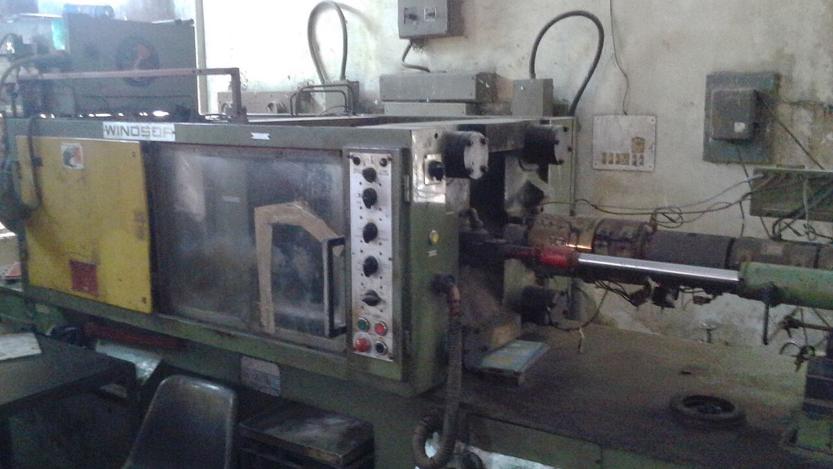
When a new mold is hung on a machine, the easiest route is to copy the settings of "a similar mold". Sometimes that works; more often it turns into hours of trial and error. The faster route is to enter the values in a fixed order, each one based on a reason. The sequence below is a roadmap from the first shot to stable production.
1. Material and drying
The first step is to open the material's technical data sheet (TDS). The melt temperature range, mold temperature range, drying conditions and often the recommended back pressure are listed there.
If hygroscopic materials (PA, PC, PBT, PET, ABS) are molded without drying, splay, brittleness and dimensional problems cannot be fixed by settings. For drying time and temperature, see the material drying guide. Starting temperatures by material are in the materials guide.
2. Barrel and mold temperatures
- Barrel profile: A profile rising from the feed zone towards the nozzle is generally used. The feed zone is kept lower so that pellets do not melt early and bridge. The nozzle should be hot enough not to cool the melt but not so hot that it drools.
- Melt temperature: Start in the middle of the data sheet range. Check the actual melt temperature by measuring an air shot; the set value on the screen is not the same as the melt.
- Mold temperature: What matters is the temperature measured on the mold surface, not the value entered on the temperature controller. In semi-crystalline materials (PP, PA, POM, PBT), mold temperature directly affects shrinkage and crystallinity; see amorphous versus semi-crystalline polymers.
Adjusting before the temperatures have settled is wasted effort. Wait until the mold and barrel have reached target and stayed stable for several shots.
3. Shot size, cushion and decompression
The shot volume is the volume of the parts plus the runner. Dividing the part weight by the melt density gives the volume, and dividing that by the screw cross-section gives the metering stroke. In practice:
- The process is most stable when the metering stroke is roughly 1–3 times the screw diameter. A very short stroke reduces metering accuracy; a very long stroke harms melt homogeneity and increases residence time in the barrel. For machine selection, see shot volume and screw diameter.
- The cushion (the melt left in front of the screw at the end of holding) is usually targeted at 3–10 mm. If the cushion drops to zero, holding pressure cannot reach the part; if it is too large, melt sits in the barrel unnecessarily.
- Decompression (suck-back) should be just enough to stop the nozzle drooling, usually a few millimeters. More than that draws air into the nozzle and causes splay.
4. Back pressure and screw speed
Back pressure is the pressure that resists the screw moving back during metering; it homogenizes the melt and drives out air. Start low and increase in steps if there are color mixing or melt homogeneity problems. Excessive back pressure causes degradation in heat-sensitive materials and long metering times.
Screw speed only needs to be high enough for metering to finish within the cooling time. Anything faster just adds shear heat to the melt. Screw surface speed is used as the measure: v = π × D × n / 60. Lower surface speeds are chosen for heat-sensitive materials (such as PVC, PC, POM). The goal: metering finishes 1–2 seconds before cooling ends.
5. Injection speed
Speed determines how long the melt takes to fill the cavity. Instead of guessing, run a viscosity curve test: record fill time and peak pressure at different speeds and choose a speed from the region where relative viscosity levels off. Filling is then less affected when the material lot changes. Details: viscosity curve test and speed selection.
Keep the injection pressure limit high enough for the machine to actually achieve the set speed. A speed profile that hits the pressure limit is not the set speed but the speed the pressure allows.
6. Filling and V/P transfer
Make the first shots with holding pressure and time at zero and fill the part step by step. The aim is for the filling phase to fill the part to about 95–98% by volume; the holding phase completes the rest. This defines the V/P transfer point by screw position.
These fill-only parts also show you the flow path, the last place to fill and where vents are needed. If you see burn marks or short shots at the last place to fill, the problem may be venting rather than speed; see mold venting. For the logic of the transfer setting: V/P switchover and holding settings.
7. Holding pressure and time
- Holding pressure: Start at about 50–70% of the peak filling pressure. Increase it if there are sink marks; reduce it if there is flash, parts sticking or oversized dimensions. Finding the lower and upper limits of the acceptable window and running in the middle makes the process robust against variation.
- Holding time: It should last until the gate freezes; after that it is wasted seconds. Find the right time by weighing the part: gate freeze study.
8. Cooling time and clamp force
Cooling time is the largest part of the cycle and grows with the square of the wall thickness. Set the starting value by calculation rather than by guess, then shorten it based on whether the part warps after ejection and on its dimensions.
Clamp force is calculated from the projected area and the cavity pressure. Far more force than needed crushes the mold, closes the vents and wastes energy; too little causes flash. For the calculation: how to calculate clamp tonnage.
You can calculate these two values and the other starting values for the machine from the part dimensions and material with the process analysis.
9. Stabilizing and recording
Once the settings are complete, take at least 15–20 shots and watch part weight, cushion, fill time and peak pressure. If these values are constant from shot to shot, the process is stable. Then move on to dimensional checks.
Finally, record the working setup. To avoid starting from zero at the next setup, write the values together with the measured melt and mold temperatures in the mold log; for defects that appear, the defect diagnosis wizard ranks causes by likelihood.
For a step-by-step plan for the first trial of a new mold, see the T1 mold trial checklist.
Is something missing or wrong in this article? .