Cutting cycle time: 10 checkpoints that save seconds without hurting quality
Trying to shorten the cycle without measuring where the time goes ends in scrap. The places to check, in order, in cooling, holding, screw recovery and mold movements.
One second sounds small, but on a 20-second cycle it means 5% more parts from the same machine. Shortening the cycle at random, however, comes back as sink, warpage and dimensional drift. The right approach is to break the time into its parts first and start with the largest one.
Measure first: where does the cycle go?
Using the machine display or a stopwatch, split one cycle into: mold close and clamp build-up, injection (filling), holding, cooling (screw recovery happens within it), mold opening, ejection and part removal. For most parts cooling is the largest item; for thin-wall packaging parts, however, mold movements and the robot can be decisive.
10 checkpoints
- Set holding time from gate freeze. Once the gate has frozen, holding pressure adds nothing to the cavity. Run a gate freeze study and set holding time to the freeze point plus a small margin. See V/P switchover and holding
- Calculate cooling, don't guess. Cooling time rises with the square of wall thickness; the thickest area sets the cycle. See Why cooling time grows with the square of wall thickness
- Don't eject the part colder than necessary. A part can be ejected once it is cool enough not to deform or show ejector marks. The rest of the cooling can happen outside the mold; check dimensions after 24 hours.
- Check the mold water. Is the flow rate sufficient, is the inlet-outlet temperature difference small (usually below 2–3 °C is the target), is there scale in the channels? Switching circuits from series to parallel and descaling are often the cheapest gains. See Cooling channel types
- Find the hot spot. Measure the surface with a non-contact thermometer or thermal camera when the mold opens. If one core or corner is clearly hotter, it is setting the cycle; consider a baffle, bubbler, high-conductivity insert or conformal cooling there.
- Fit screw recovery within cooling. If metering takes longer than cooling, the screw sets the cycle. Increase screw speed, keep back pressure reasonable; if necessary consider a machine with a larger screw. See Matching a machine to a mold
- Profile mold movements. Make long travel fast and the start/end slow; don't keep the mold protection (low-pressure closing) zone longer than necessary.
- Run movements in parallel. Where possible, start ejector, core pull and robot movements while the mold is opening; start screw recovery as soon as holding ends. Use the machine's parallel-movement capability.
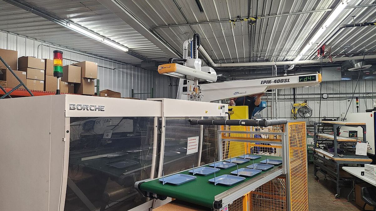
- Shorten robot and take-out time. Time the robot spends inside the mold adds directly to the cycle. Review the pick point, acceleration profiles and handshake signals.
- Don't forget the runner. In cold runner molds the thickest section is sometimes not the part but the runner and sprue. Don't oversize the runner; check sprue bushing cooling.
After every change
Change one thing at a time, then measure: part weight, critical dimensions (after 24 hours), appearance. Seconds gained must not be paid back as extra scrap.
If weight and dimensions do not drift, record the new setting as the reference process; at the next mold change you start from the same point. The Mold log can be used for this.
Is something missing or wrong in this article? .