Gate types and gate location: edge, tunnel, pin-point, film and valve gates
The type, size and location of the gate determine filling, weld lines, sink and warpage. Which gate should you choose, and where should it go?
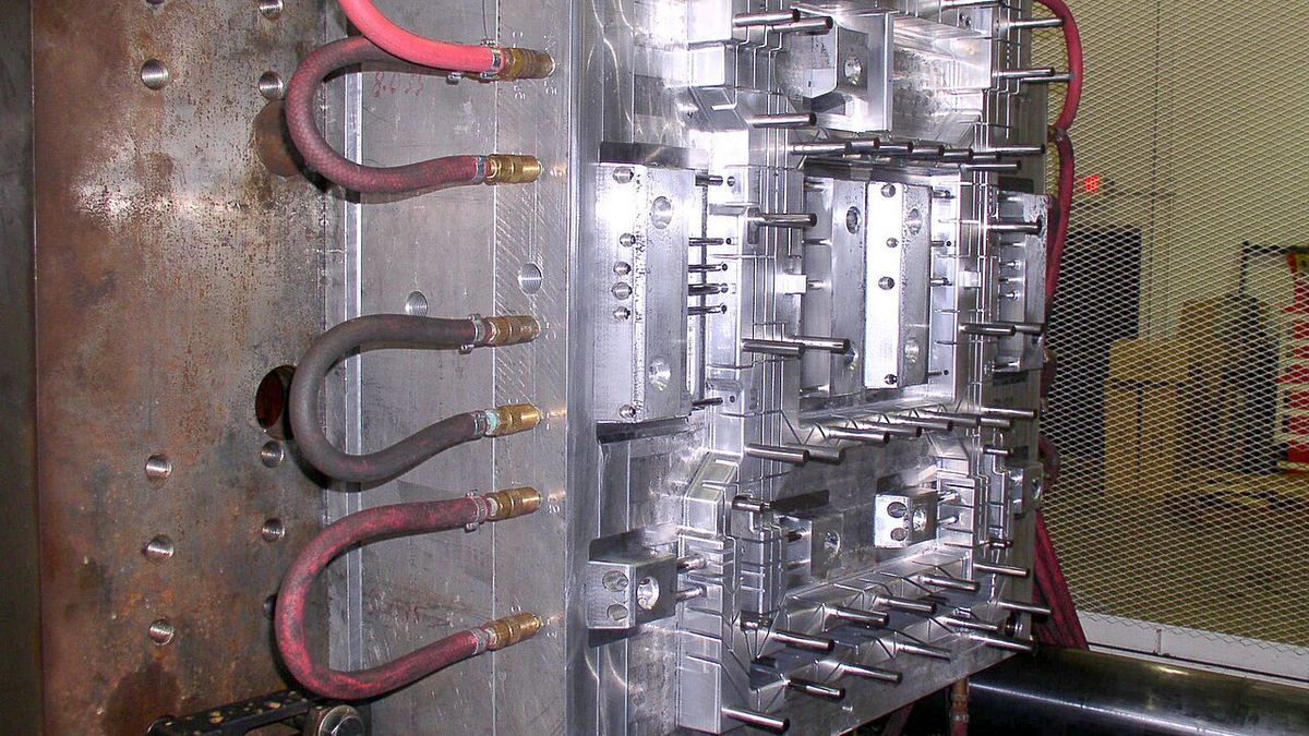
The gate is the restriction through which the melt enters the cavity from the runner. It looks like a detail, but the gate largely determines how the part fills, where weld lines appear, whether holding pressure reaches thick sections and how much the part warps. Moving a gate after the steel is cut is expensive; the decision belongs in the design phase.
Common gate types
| Gate | Typical use | Advantage | Watch out |
|---|---|---|---|
| Edge (side) gate | Most parts in two-plate molds | Simple, cheap, easy to adjust | Leaves a vestige; removed by hand or cutter |
| Tunnel (submarine) gate | Small-medium parts, automatic production | Shears off during ejection | High shear; breakage/clogging with glass-filled and brittle materials |
| Banana (curved tunnel) gate | Entry from a hidden inner surface | No mark on the visible face | Needs a flexible material; hard to machine |
| Pin-point gate | Three-plate mold | Separates automatically, small mark | More runner scrap, more expensive mold |
| Film / fan gate | Wide, flat parts | Even flow front, less warpage | Needs trimming; trimmed edge visible |
| Diaphragm (disk) gate | Cylindrical, concentric parts | No weld line, good roundness | Centre must be cut out |
| Hot runner / valve gate | High volume, cosmetic parts | No runner scrap; sequential opening controls weld lines | Investment and maintenance cost |
For the hot vs cold runner decision, see: Hot runner or cold runner?
Where should the gate go?
- Into the thickest section. Melt should flow from thick to thin. If the gate is in a thin area, it freezes early and holding pressure cannot reach the thick region; the result is sink marks and voids.
- So the weld line lands in the right place. Two flow fronts meet behind holes and bosses. Move the gate so this line falls in a hidden, non-load-bearing area in front of a vent. More: Weld lines and air traps
- To prevent jetting. If melt shoots into open space from the gate, a snake-like mark forms. Place the gate against a wall, pin or rib so the flow immediately hits a surface and spreads.
- To balance flow length. On long parts, gating in the middle or at several symmetrical points instead of one end lowers the required pressure and warpage. In multi-cavity molds the runner to each cavity must be balanced.
- Away from cosmetic surfaces. The gate vestige, flow marks and blush around the gate should not be on a visible face.
- With fibre orientation in mind for glass-filled grades. Fibres align with the flow; shrinkage is low along the flow and higher across it. Gate location therefore drives both dimensions and warpage.
Gate size
For edge gates, gate thickness is usually chosen at 50–80% of the part's wall thickness. Too small: early freeze, high shear heating (burns, discoloration), sink. Too large: late freeze, long holding time, difficult trimming and a large vestige. Measure when the gate freezes with a gate freeze study during mold trials and set the holding time accordingly: V/P switchover and holding
Cut the gate small on the first trial and open it up if needed. Removing steel is easy; adding it back is not.
Quick checklist
- Is the gate in the thickest area?
- Where does the weld line fall, and is there a vent there? (Venting)
- Does the flow from the gate hit a surface?
- Are runners balanced in multi-cavity molds?
- Is the gate vestige on a visible face?
- Has the gate freeze time been measured?
Is something missing or wrong in this article? .